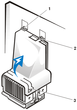
Figure 2. Cooling Fan, Heat Sink
Assembly, and Microprocessor
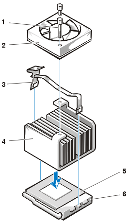 |
| 1 |
Thumbscrews (2) |
| 2 |
Cooling fan |
| 3 |
Metal securing clip |
| 4 |
Heat sink assembly |
| 5 |
Microprocessor |
| 6 |
ZIF socket |
|
- Release the metal securing clip that holds the heat sink assembly to
the microprocessor zero insertion force (ZIF) connector.
Press down on the folded part of the clip with a small screwdriver to
release the clip (see Figure 3). The securing clip hooks over
tabs on the sides of the socket.
- Remove the heat sink assembly from the microprocessor.
Figure 3. Microprocessor Heat Sink
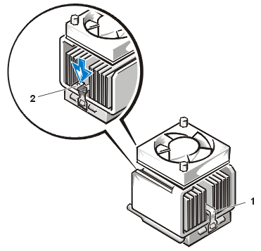 |
| 1 |
Metal securing clip |
| 2 |
Press here to release securing clip |
|
NOTICE: Be careful not to bend any of the pins when you
remove the microprocessor from its socket. Bending the pins can permanently damage the
microprocessor.
- Remove the microprocessor from the ZIF socket.
The microprocessor socket is a ZIF socket with a lever-type handle that secures the
microprocessor in, or releases it from, the socket.
NOTICE: Ground yourself by touching an unpainted metal surface on the back of
the computer.
To remove the microprocessor, pull the ZIF socket release lever straight out until the
microprocessor is released (see Figure 4). Then remove the
microprocessor by lifting it straight up from the socket. Leave the release lever extended
so that the socket is ready for installation of the new microprocessor.
Figure 4. Removing the
Microprocessor
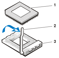 |
| 1 |
Microprocessor |
| 2 |
Socket release lever |
| 3 |
ZIF socket |
|
NOTICE: Ground yourself by touching an unpainted metal
surface on the back of the computer.
- Unpack the new microprocessor.
If any of the pins on the chip appear to be bent, see "Getting Help" for instructions on obtaining technical
assistance.
- Align pin-1 (the beveled corner) of the microprocessor with the pin-1
corner of the microprocessor ZIF socket (see Figure 5).
 |
NOTE: You must identify the pin-1 corner to
correctly position the microprocessor. |
Figure 5. Installing the
Microprocessor Chip
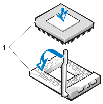 |
| 1 |
Pin-1 corners of chip and socket aligned
|
|
NOTICE: When you place the microprocessor in the ZIF socket,
be sure that all of the pins go into the corresponding holes on all sides of the socket.
Be careful not to bend any of the pins when you install the microprocessor in the ZIF
socket. Bending the pins can permanently damage the microprocessor.
NOTICE: You must position the microprocessor correctly in
the socket to avoid permanent damage to the microprocessor and the computer when you turn
on the system.
- Install the microprocessor in the ZIF socket (see Figure 5):
- If the release lever on the microprocessor socket is not all the way
out, move it to that position now.
- With the pin-1 corners of the microprocessor and socket aligned,
align the pins on the microprocessor with the holes in the socket.
- Lightly set the microprocessor in the socket and make sure all pins
are headed into the correct holes. Because your system uses a ZIF microprocessor socket,
there is no need to use force (which could bend the pins if the microprocessor is
misaligned). When the microprocessor is positioned correctly, press it with minimal
pressure to seat it.
- When the microprocessor is fully seated in the socket, pivot the
socket release lever back toward the socket until it snaps into place, which secures the
microprocessor.
NOTICE: Ground yourself by touching an unpainted metal
surface on the back of the computer.
- Unpack the heat sink included in your upgrade kit and install it:
- Peel the release liner from the adhesive tape that is attached to the
bottom of the heat sink.
- Place the heat sink assembly on top of the microprocessor.
- Orient the securing clip as shown in Figure 6, and hook the unhinged end of the clip over
the tab on the top edge of the socket.
- Press down on the hinged end of the clip to snap the clip over the
tab on the bottom edge of the socket.
Figure 6. Installing the
Heat Sink
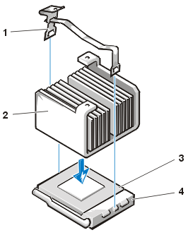 |
| 1 |
Securing clip |
| 2 |
Heat sink |
| 3 |
Microprocessor |
| 4 |
ZIF socket |
|
- If you are working in a small-form-factor or low-profile chassis
system, replace the cooling fan on top of the heat sink assembly, and secure the fan with
the two thumbscrews.
- Reconnect the cooling fan power cable to its system board connector.
- If you are working in the mini-tower chassis system, replace the
airflow shroud:
- Place the airflow shroud over the processor.
- Fit the mouth of the shroud into the alignment slot on the left side
of the fan and between the fan and the power supply bracket on the right.
- Lift up on the pair of tabs on the sides of the shroud and lower it
onto the processor/heat sink assembly until it clicks into place. The shroud should engage
the top of the processor socket.
- Replace or rotate the power supply back into position, making sure
that the securing tab snaps into position.
- Replace the computer cover, and then reconnect your computer and
peripherals to their electrical outlets and turn them on.
As the system boots, it detects the presence of the new
microprocessor and automatically changes the system configuration information in System
Setup.