Dell™ Latitude™ D610 User's Guide
This chapter provides procedures for removing and installing the components in your computer. Unless otherwise noted, each procedure assumes that the following conditions exist:
The procedures in this document may require the following tools:

|
NOTICE: To avoid losing data, save and close any open files and exit any open programs before you turn off your computer. |
The computer turns off after the operating system shutdown process finishes.
Use the following safety guidelines to help protect your computer from potential damage and to help ensure your own personal safety.

|
CAUTION: Before you begin any of the procedures in this section, follow the safety instructions in the Product Information Guide. |
|
|
CAUTION: Handle components and cards with care. Do not touch the components or contacts on a card. Hold a card by its edges or by its metal mounting bracket. Hold a component such as a processor by its edges, not by its pins. |
|
|
NOTICE: Only a certified service technician should perform repairs on your computer. Damage due to servicing that is not authorized by Dell is not covered by your warranty. |
|
|
NOTICE: When you disconnect a cable, pull on its connector or on its strain-relief loop, not on the cable itself. Some cables have a connector with locking tabs; if you are disconnecting this type of cable, press in on the locking tabs before you disconnect the cable. As you pull connectors apart, keep them evenly aligned to avoid bending any connector pins. Also, before you connect a cable, ensure that both connectors are correctly oriented and aligned. |
|
|
NOTICE: To avoid damaging the computer, perform the following steps before you begin working inside the computer. |
|
|
NOTICE: To disconnect a network cable, first unplug the cable from your computer and then unplug it from the network wall jack. |
|
|
NOTICE: To avoid damaging the system board, you must remove the main battery before you service the computer. |
You can increase your computer memory by installing memory modules on the system board. See "Specifications" for information on the memory supported by your computer. Install only memory modules that are intended for your computer.
|
|
CAUTION: Before you begin any of the procedures in this section, follow the safety instructions in the Product Information Guide. |
|
|
NOTICE: If your computer has only one memory module, install the memory module in the connector labeled "DIMMA." |
|
|
NOTICE: If you remove your original memory modules from the computer during a memory upgrade, keep them separate from any new modules that you may have, even if you purchased the new modules from Dell. If possible, do not pair an original memory module with a new memory module. Otherwise, your computer may not function at optimal performance. |

|
NOTE: Memory modules purchased from Dell are covered under your computer warranty. |
Your computer has two user-accessible SODIMM sockets, one accessed from beneath the keyboard (DIMM A), and the other accessed from the bottom of the computer (DIMM B).
To add or replace a memory module in the DIMM A connector:
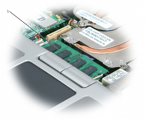
|
1 |
memory module (DIMM A) |
|
|
NOTICE: To prevent damage to the memory module connector, do not use tools to spread the memory-module securing clips. |
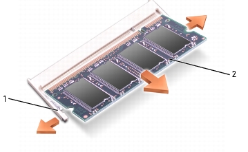
|
1 |
securing clips (2 per connector) |
|
2 |
memory module |
|
|
NOTICE: If you need to install memory modules in two connectors, install a memory module in the connector labeled "DIMMA" before you install a module in the connector labeled "DIMMB." Insert memory modules at a 45-degree angle to avoid damaging the connector. |
|
|
NOTE: If the memory module is not installed properly, the computer may not boot properly. No error message indicates this failure. |
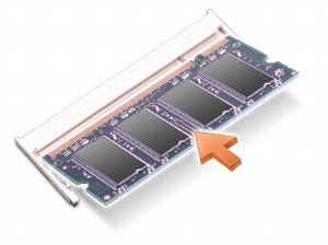
To add or replace a memory module in the DIMM B connector:
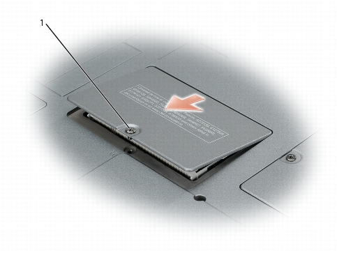
|
1 |
captive screw |
|
|
NOTICE: To prevent damage to the memory module connector, do not use tools to spread the memory-module securing clips. |
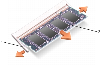
|
1 |
securing clips (2 per connector) |
|
2 |
memory module |
|
|
NOTICE: If you need to install memory modules in two connectors, install a memory module in the connector labeled "DIMMA" before you install a module in the connector labeled "DIMMB." Insert memory modules at a 45-degree angle to avoid damaging the connector. |
|
|
NOTE: If the memory module is not installed properly, the computer may not boot properly. No error message indicates this failure. |
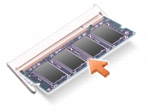
|
|
NOTICE: If the cover is difficult to close, remove the module and reinstall it. Forcing the cover to close may damage your computer. |
As the computer boots, it detects the additional memory and automatically updates the system configuration information.
To confirm the amount of memory installed in the computer:
If you ordered the optional modem at the same time that you ordered your computer, the modem is already installed.
|
|
CAUTION: Before you begin any of the procedures in this section, follow the safety instructions in the Product Information Guide. |
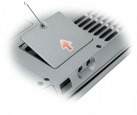
|
1 |
captive screw |
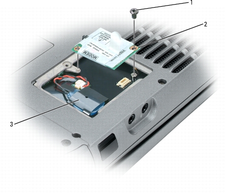
|
1 |
screw |
|
2 |
modem |
|
3 |
coin-cell battery |
|
|
NOTICE: The connectors are keyed to ensure correct insertion. If you feel resistance, check the connectors and realign the card. |
If you ordered a Mini PCI card with your computer, the card is already installed.
|
|
CAUTION: Before you begin any of the procedures in this section, follow the safety instructions in the Product Information Guide. |
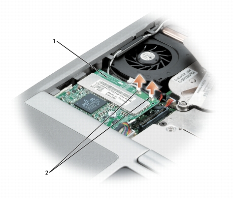
|
1 |
Mini PCI card |
|
2 |
antenna wires (2) |
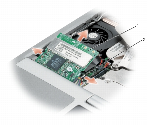
|
1 |
Mini PCI card |
|
2 |
metal securing tabs (2) |
|
|
NOTICE: The connectors are keyed to ensure correct insertion. If you feel resistance, check the connectors and realign the card. |
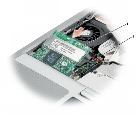
|
1 |
Mini PCI card |
|
2 |
metal securing tabs (2) |
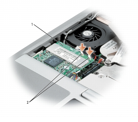
|
1 |
Mini PCI card |
|
2 |
antenna wires (2) |
|
|
NOTICE: To avoid damaging the Mini PCI card, never place cables on top of or under the card. |
|
|
CAUTION: If you remove the hard drive from the computer when the drive is hot, do not touch the metal housing of the hard drive. |
|
|
CAUTION: Before working inside your computer, follow the safety instructions in the Product Information Guide. |
|
|
NOTICE: To prevent data loss, turn off your computer before removing the hard drive. Do not remove the hard drive while the computer is on, in standby mode, or in hibernate mode. |
|
|
NOTICE: Hard drives are extremely fragile; even a slight bump can damage the drive. |
|
|
NOTE: Dell does not guarantee compatibility or provide support for hard drives from sources other than Dell. |
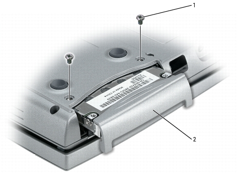
To replace the hard drive in the hard drive bay:
|
1 |
screws (2) |
|
2 |
hard drive |
|
|
NOTICE: When the hard drive is not in the computer, store it in protective antistatic packaging. See "Protecting Against Electrostatic Discharge" in the Product Information Guide. |
Save the original packaging for storing or shipping the hard drive.
|
|
NOTICE: Use firm and even pressure to slide the drive into place. If you use excessive force, you may damage the connector. |
|
|
CAUTION: Before performing the following procedures, read the safety instructions in your Product Information Guide. |
|
|
NOTICE: To avoid electrostatic discharge, ground yourself by using a wrist grounding strap or by periodically touching an unpainted metal surface (such as the back panel) on the computer. |
|
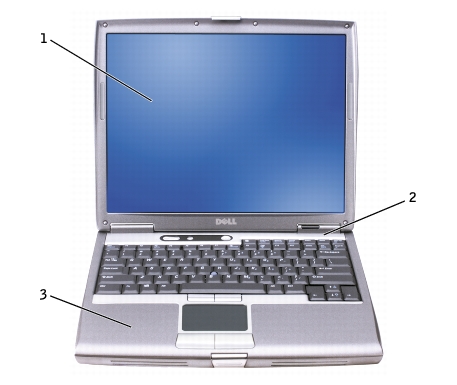
1 |
display |
|
2 |
center control cover |
|
3 |
computer base |
|
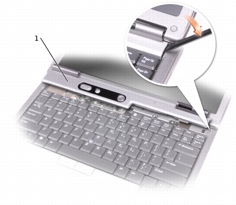
1 |
center control cover |
|
|
NOTICE: The keycaps on the keyboard are fragile, easily dislodged, and time-consuming to replace. Be careful when removing and handling the keyboard. |
|
|
NOTE: Lift the keyboard carefully in step b to ensure that you do not pull on the keyboard wire. |
|
|
NOTE: When you replace the keyboard, ensure that the keyboard tabs are completely in place to avoid scratching the palm rest. |
|
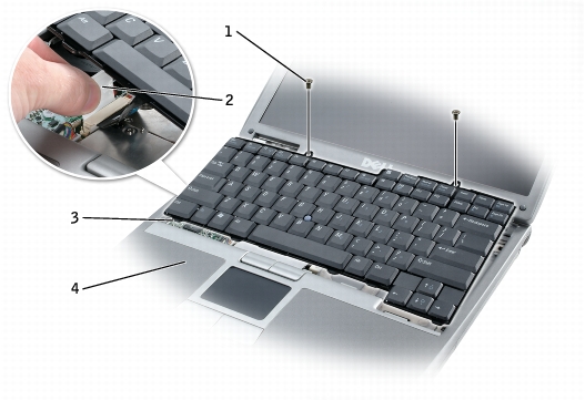
1 |
M2.5 x 6-mm screws (2) |
|
2 |
keyboard connector pull-tab |
|
3 |
keyboard tabs |
|
4 |
palm rest |
|
|
CAUTION: Before performing the following procedures, read the safety instructions in your Product Information Guide. |
|
|
NOTICE: To avoid electrostatic discharge, ground yourself by using a wrist grounding strap or by periodically touching a connector on the back panel of the computer. |
|
|
NOTICE: To avoid damaging the system board, you must remove the main battery before you begin working inside the computer. |
If you ordered an internal card with Bluetooth wireless technology with your computer, it is already installed.
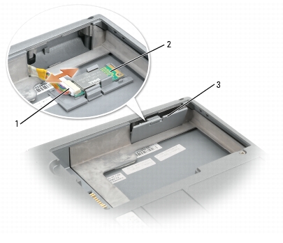
|
1 |
card connector |
|
2 |
card |
|
3 |
door |
|
|
CAUTION: Before performing the following procedures, read the safety instructions in your Product Information Guide. |
|
|
NOTICE: To avoid electrostatic discharge, ground yourself by using a wrist grounding strap or by periodically touching a connector on the back panel of the computer. |
|
|
NOTICE: To avoid damaging the system board, you must remove the main battery before you begin working inside the computer. |
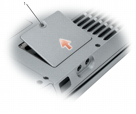
|
1 |
captive screw |
|
|
NOTICE: To avoid damaging the system board, make sure you do not remove the plastic film between the battery and the system board as you remove the double-sided tape from the coin-cell battery. |
|
|
NOTICE: To avoid damaging the system board or modem card, retain the double-sided tape and secure the replacement coin-cell battery to the plastic film between the battery and the system board. |
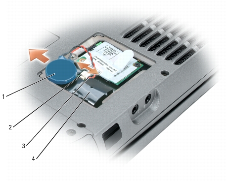
|
1 |
coin-cell battery |
|
2 |
cable connector |
|
3 |
battery cable connector |
|
4 |
coin-cell battery pocket |
