Expansion Cards
Dell™ PowerEdge™ 2550 Systems Installation and Troubleshooting Guide
Upgrading the Microprocessor or Installing a Secondary Microprocessor
Activating the Integrated RAID Controller
This section describes how to install expansion cards, memory, and microprocessors and how to activate the system's integrated redundant array of independent disks (RAID) controller. Instructions for replacing the system battery are also included.
 |
WARNING: Before you perform the procedures in this section, you must turn off the system and disconnect it from its electrical outlet. For more information, see "Safety First—For You and Your Computer" in "Checking Inside the System." |
Use Table 8-1 and Figure 8-1 to locate the system board features.
Table 8-1. System Board Connectors and Sockets
|
Connector or Socket |
Description |
|---|---|
|
BACKPLANE |
SCSI backplane board interface cable connector |
|
BATTERY |
Battery connector |
|
COMn |
Serial port connectors |
|
DIMM_x |
Memory module sockets |
|
DIMM_RAID |
Memory module socket for integrated RAID controller |
|
INTRUS |
Intrusion-alarm switch connector |
|
KYBD |
Keyboard connector |
|
MOUSE |
Mouse connector |
|
NICn |
NIC connector |
|
PANEL |
System control panel connector |
|
PARALLEL |
Parallel port connector |
|
POWERn |
Power connectors |
|
PROC_n |
Microprocessor connectors |
|
RAID_KEY |
Socket for integrated RAID controller hardware key |
|
RAID_BATTERY |
Connector for integrated RAID controller battery |
|
RISER |
PCI riser board connector |
|
SCSIA, SCSIB |
SCSI host adapter connectors |
|
USBn |
USB connectors |
|
VGA |
Video connector |
|
VRMn |
Primary and secondary VRM connectors |
|
NOTE: For the full name of an abbreviation or acronym used in this table, see "Abbreviations and Acronyms." |
|
Figure 8-1. System Board Features
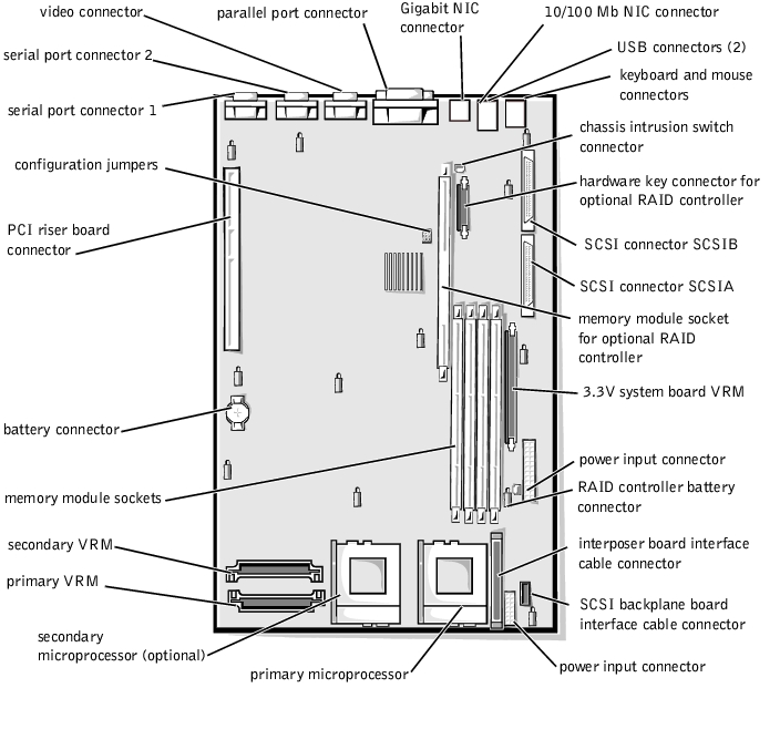
Expansion cards are installed on the system's riser board (see Figure 8-2). The riser board plugs into the RISER connector on the system board (see Figure 8-1) and is considered an extension of the system board.
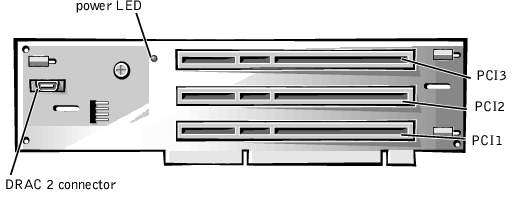
The riser board contains three full-length 64-bit, 33-megahertz (MHz), Peripheral Component Interconnect (PCI) expansion-card connectors. All three expansion card connectors support 5-V or universal PCI cards. Connector PCI2 supports an optional Dell OpenManage™ Remote Assistant Card 2 (DRAC 2).
Figure 8-2. Riser-Board Expansion-Card Connectors
To install an expansion card, perform the following steps.
|
WARNING: Before you perform this procedure, you must turn off the system and disconnect it from its AC power source. For more information, see "Safety First—For You and Your Computer" in "Checking Inside the System." |
|
WARNING: See "Protecting Against Electrostatic Discharge" in the safety instructions in your System Information document. |
See the documentation that came with the expansion card for information on configuring the card, making internal connections, or otherwise customizing the card for your system.
 |
NOTE: Verify that the power LED on the riser board (see Figure 8-2) is off before removing the expansion-card cage. |
Figure 8-3. Installing an Expansion Card
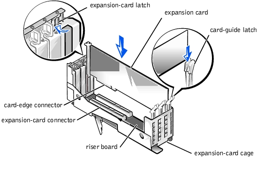
Position the expansion-card cage so that the riser board lies horizontally on your work surface. Insert the card-edge connector firmly into the expansion-card connector on the riser board until the card is fully seated.
To remove an expansion card, perform the following steps.
|
WARNING: Before you perform this procedure, you must turn off the system and disconnect it from its electrical outlet. For more information, see "Safety First—For You and Your Computer" in "Checking Inside the System." |
|
NOTE: Installing a filler bracket over an empty expansion slot is necessary to maintain Federal Communications Commission (FCC) certification of the system. The brackets also keep dust and dirt out of the system and aid in proper cooling and airflow inside the system. |
The four dual in-line memory module (DIMM) sockets on the system board (see Figure 8-1) can accommodate from 128 megabytes (MB) to 4 gigabytes (GB) of registered synchronous dynamic random-access memory (SDRAM).
The system is upgradable to 4 GB by installing combinations of 64-,128- 256-, 512-MB, or 1-GB registered memory modules. You can purchase memory upgrade kits from Dell as needed.
|
NOTE: The memory modules must be PC-133 compliant. |
Starting with the socket nearest to the system power supply (or supplies), the memory module sockets are labeled "DIMM_A" through "DIMM_D" (see Figure 8-4). When you install memory modules, follow these guidelines:
Figure 8-4. Memory Module Sockets
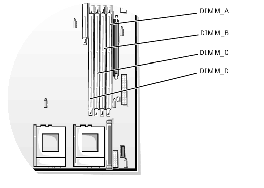
Table 8-2 illustrates several sample memory configurations based on these guidelines.
Table 8-2. Sample Memory Module Configurations
To perform a memory upgrade to the system board, perform the following steps.
|
WARNING: Before you perform this procedure, you must turn off the system and disconnect it from its electrical outlet. For more information, see "Safety First—For You and Your Computer" in "Checking Inside the System." |
|
WARNING: See "Protecting Against Electrostatic Discharge" in the safety instructions in the System Information document. |
Figure 8-1 shows the general location of the memory module sockets on the system board. Figure 8-4 shows the order of the memory module sockets.
To install a memory module, perform the following steps:
Figure 8-5. Installing a Memory Module
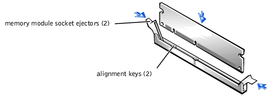
The memory module socket has two alignment keys that allow the memory module to be installed in the socket in only one way.
To remove a memory module, press down and outward on the ejectors on each end of the socket until the memory module pops out of the socket (see Figure 8-6).
Figure 8-6. Removing a Memory Module

To take advantage of future options in speed and functionality, you can add a second processor or replace either the primary or secondary processor.
 |
NOTICE: The second processor must be of the same type and speed as the first processor. |
Each processor and its associated level 2 (L2) cache memory are contained in a Flip Chip Pin Grid Array (FC-PGA) package that is installed in a zero insertion force (ZIF) socket on the system board. The following subsection describes how to install or replace the microprocessor in either the primary or secondary processor connector.
In addition to the ZIF socket for the primary microprocessor on the system board, there is a second ZIF socket to accommodate a secondary microprocessor. The secondary microprocessor must have the same operating frequency as the primary micro-processor.
The following items are included in the microprocessor upgrade kit:
|
NOTICE: Dell recommends that only a technically knowledgeable person perform this procedure. |
|
NOTICE: See "Protecting Against Electrostatic Discharge" in the safety instructions in the System Information document. |
|
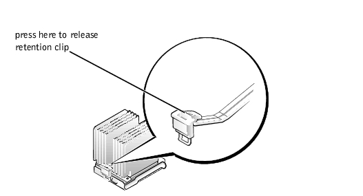
NOTICE: Never remove the heat sink from a microprocessor unless you intend to remove the microprocessor. The heat sink is necessary to maintain proper thermal conditions. |
 |
CAUTION: The microprocessor chip and heat sink can become extremely hot. Be sure that the microprocessor has had sufficient time to cool before handling. |
|
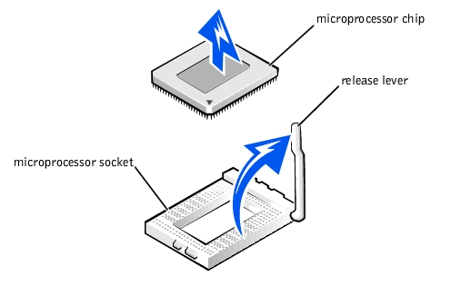
NOTICE: Be careful not to bend any of the pins when removing the microprocessor chip. Bending the pins can permanently damage the microprocessor chip. |
Leave the release lever up so that the socket is ready for the new microprocessor.
Figure 8-8. Removing the Microprocessor
|
NOTICE: Be careful not to bend any of the pins when unpacking the microprocessor chip. Bending the pins can permanently damage the microprocessor chip. |
If any of the pins on the microprocessor appear bent, see "Getting Help" for instructions on obtaining technical assistance from Dell.
|
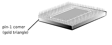
NOTICE: Identifying the pin-1 corners is critical to positioning the chip correctly. |
Figure 8-9. Pin-1 Identification
|
NOTICE: Positioning the microprocessor incorrectly can permanently damage the chip and the system when you turn on the system. |
|
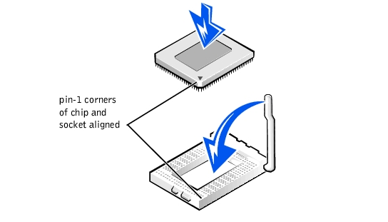
NOTICE: When placing the microprocessor chip in the socket, be sure that all of the pins on the chip go into the corresponding holes of the socket. Be careful not to bend the pins. |
Because the system uses a ZIF microprocessor socket, there is no need to use force (which could bend the pins if the chip is misaligned). When the chip is positioned correctly, it should drop down into the socket with minimal pressure.
Figure 8-10. Installing the Microprocessor Chip
|
NOTE: To avoid possible damage to the microprocessor, you must align the heat sink so that the triangular mark on the heat sink points toward the triangular mark on the system board. |
Figure 8-11. Installing the Heat Sink
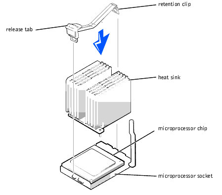
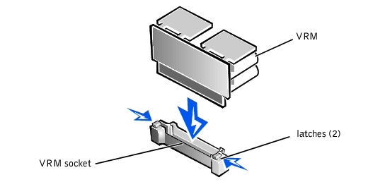
Figure 8-12. Installing the VRM
|
NOTE: After you remove and replace the cover, the chassis intrusion detector will cause an alert message to be displayed at the next system start-up. |
|
NOTE: If a setup password has been assigned by someone else, contact your network administrator for information on resetting the chassis intrusion detector. |
To activate the integrated PowerEdge™ Expandable RAID Controller (PERC) 3/Di, perform the following steps.
|
WARNING: Before you perform this procedure, you must turn off the system and disconnect it from its electrical outlet. For more information, see "Safety First—For You and Your Computer" in "Checking Inside the System." |
|
NOTICE: To avoid possible data loss, back up all data on the hard-disk drives before changing the mode of operation of the integrated SCSI controller from SCSI to RAID. |
|
WARNING: See "Protecting Against Electrostatic Discharge" in the safety instructions in the System Information document. |
|
NOTE: Verify that the power LED on the riser board (see Figure 8-2) is off before removing the card cage. |
See Figure 8-1 for the location of the socket on the system board.
The memory module socket has two alignment keys that allow the memory module to be installed in the socket in only one way.
|
NOTE: The RAID controller memory module must be an unbuffered memory module, rated to run at 100 MHz or faster. Do not substitute registered memory modules such as those used for system memory. |
Figure 8-13. Installing the RAID Hardware Key
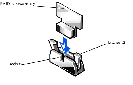
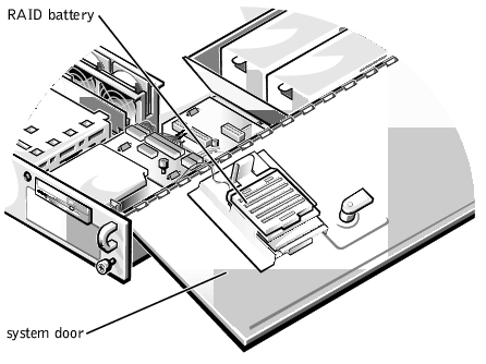
Figure 8-14. Installing the RAID Battery
The system battery maintains system configuration, date, and time information in a special section of memory when you turn off the system. The operating life of the battery ranges from 2 to 5 years, depending on how you use the system (for example, if you keep the system on most of the time, the battery gets little use and thus lasts longer). You may need to replace the battery if an incorrect time or date is displayed during the boot routine along with the following or similar message:
Time-of-day not set -- please run SETUP program
Strike the F1 key to continue, F2 to run the setup utility
or
System CMOS checksum bad -- Run SETUP
Strike the F1 key to continue, F2 to run the setup utility
or
Invalid configuration information -- please run SETUP program
Strike the F1 key to continue, F2 to run the setup utility
To determine if the battery needs to be replaced, re-enter the time and date through the System Setup program (see "Using the System Setup Program" in the User's Guide for instructions). Turn off and disconnect the system from the electrical outlet for a few hours, and then reconnect and turn the system on again. Enter the System Setup program. If the date and time are not correct in the System Setup program, replace the battery.
|
NOTE: Some software may cause the system time to speed up or slow down. If the system seems to operate normally except for the time kept in the System Setup program, the problem may be caused by software rather than by a defective battery. |
|
NOTE: If the system is turned off for long periods of time (for weeks or months), the nonvolatile random-access memory (NVRAM) may lose its system configuration information. This situation is not caused by a defective battery. |
You can operate the system without a battery; however, the system configuration information maintained by the battery in NVRAM is erased each time you shut down the system. Therefore, you must re-enter the system configuration information and reset the options each time the system boots until you replace the battery.
The battery is a 3.0-volt (V), coin-cell CR2032-type battery. To remove the battery, perform the following steps.
|
WARNING: Before you perform this procedure, you must turn off the system and disconnect it from its electrical outlet. For more information, see "Safety First—For You and Your Computer" in "Checking Inside the System." |
|
WARNING: There is a danger of a new battery exploding if it is incorrectly installed. Replace the battery only with the same or equivalent type recommended by the manufacturer. Discard used batteries according to the manufacturer's instructions. |
|
WARNING: See "Protecting Against Electrostatic Discharge" in the safety instructions in the System Information document. |
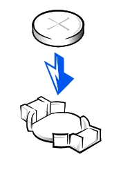
Figure 8-15. Installing the Battery