|
Overview | |
SCSI Backplane Boards |
|
Jumpers and Switches—A General Explanation | |
Interposer Board Connectors |
|
System Board Jumpers | |
Disabling a Forgotten Password |
|
System Board Labels |
This section provides specific information about the jumpers on the system board. It also provides some basic information on jumpers and switches and describes the connectors and sockets on the various boards in the system.
Jumpers and switches provide a convenient and reversible way of reconfiguring the circuitry on a printed circuit board. When installing replacement parts or reconfiguring the system, you may need to change jumper settings on the system board. You may also need to change jumper and/or switch settings on expansion cards or drives.
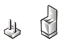
Jumpers are small blocks on a circuit board with two or more pins emerging from them. Plastic plugs containing a wire fit down over the pins. The wire connects the pins and creates a circuit. To change a jumper setting, pull the plug off its pin(s) and carefully fit it down onto the pin(s) indicated.
NOTICE: Make sure the system is turned off before you change a jumper setting. Otherwise, damage to the system or unpredictable results may occur.
A jumper is referred to as open or unjumpered when the plug is pushed down over only one pin or if there is no plug at all. When the plug is pushed down over two pins, the jumper is referred to as jumpered. The jumper setting is often shown in text as two numbers, such as 1-2. The number 1 is printed on the circuit board so that you can identify each pin number based on the location of pin 1.
Switches control various circuits or functions in the system. The switches that you are most likely to encounter are dual in-line package (DIP) switches, which are normally packaged in groups of two or more switches in a plastic case. Two common types of DIP switches are slide switches and rocker switches (see the following illustration).
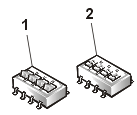
1 |
Rocker switch |
2 |
Slide switch |
Each of these switches has two positions, or settings (usually on and off). To change the setting of a slide switch, use a small, pointed object such as a small screwdriver or a straightened paper clip to slide the switch to the proper position. To change the setting of a rocker switch, use the screwdriver or paper clip to press down on the appropriate side of the switch. In either case, do not use a pen, pencil, or other object that might leave a residue on the switch.
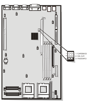
Figure 1 shows the location of the configuration jumpers on the system board. Table 1 lists the function of these jumpers.
Figure 1. System Board Jumpers
| Table 1. System-Board Jumper Settings |
| Jumper | Setting | Description | |
|---|---|---|---|
| CARDBIOS |  |
Reserved (do not change). | |
| ISA_CLR |  |
(default) | The
configuration settings are retained at system boot. The configuration settings are cleared at next system boot. If the ISA configuration settings become corrupted to the point where the system will not boot, install the jumper plug and boot the system. Remove the jumper before restoring the configuration information. |
| PASSWRD |  |
(default) | The
password feature is enabled. The password feature is disabled. |
 jumpered jumpered
 unjumpered unjumpered |
|||
Table 2 lists the connectors and sockets located on the system board.
| Table 2. System Board Connectors and Sockets |
| Connector or Socket | Description |
|---|---|
| BACKPLANE | Hot-pluggable SCSI backplane board interface cable connector |
| BATTERY | Battery connector |
| COMn | Serial port connectors; sometimes referred to as COM1 and COM2 |
| DIMM_x | Memory module sockets |
| DIMM_RAID | Memory module socket for integrated RAID controller |
| INTRUS1 | Intrusion-alarm switch connector |
| KYBD | Keyboard connector |
| MOUSE | Mouse connector |
| NICn | NIC connectors |
| PANEL | System control panel connector |
| PARALLEL | Parallel port connector; sometimes referred to as LPT1 |
| POWERn | Power connector |
| PROC_n | Microprocessor connectors |
| RAID_KEY | Socket for integrated RAID controller hardware key |
| RISER | PCI riser board connectors |
| SCSIA, SCSIB | SCSI host adapter connectors |
| USBn | USB connector |
| VGA | Video connector |
| VRMn | Primary and secondary connectors |
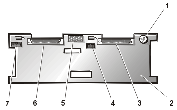
Figure 2 shows the location of the connectors on the back of the SCSI backplane board.
Figure 2. SCSI Backplane Board Connectors
|
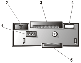
Figure 3 shows the connectors and sockets located on the interposer board.
Figure 3. Connectors on the Interposer Board
|
The system's software security features include a supervisor password and a user password, which are discussed in detail in "Using the System Setup Program" of the User's Guide. A password jumper on the system board enables these password features or disables them and clears any password(s) currently in use.
To disable a forgotten supervisor password or user password, perform the following steps.
NOTICE: See "Protecting Against Electrostatic Discharge" in your System Information document. |
 |
NOTE: If you assign a new system and/or user password with the jumper plug still removed, the system disables the new password(s) the next time it boots. |